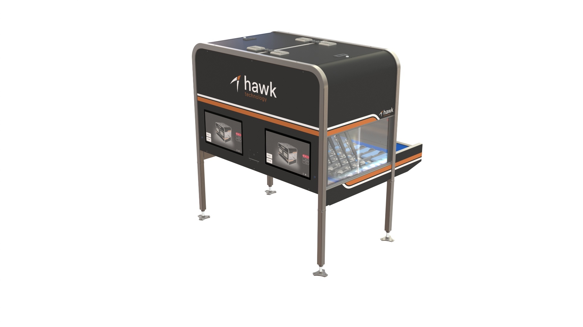
Hawk Technology Limited provides machines and technology that are designed and developed to provide reliable, state-of-the-art robotic handling and packing of apples.
This page is the complete manual for the Robotic Apple Packer: safe operation, cleaning, maintenance, and troubleshooting. Hawk Technology recommends reviewing this documentation with the technician that installs or services your equipment.
¶ General Information
¶ Manufacturer
Hawk Technology Limited
82/70 Whakatu Road
Whakatu, Hastings 4102
New Zealand
Phone: 0508 429 572
Email: info@hawktech.co.nz
¶ Conditions of Use
The machine must be used only as it was expressly designed. Any other use shall be considered improper and hence unreasonable. The company shall not be held responsible for any damage due to improper, wrong, or unreasonable use.
¶ Machine Identification
An ID plate is fitted to each machine displaying a unique serial number. This serial number, or the lane number and site name, should be used to identify the machine for service requirements.

Figure 1: ID plate attached to each machine.
¶ Product Overview
¶ General Specification
Table 1: General Technical Specification
| Description | Value |
|---|---|
| Operating voltage | 90–264 VAC 1P + N + E |
| Operating frequency | 47–63 Hz |
| Acceptable temperature range | 0°C to 40°C (32°F to 104°F) |
| Dimensions | L 1430mm × W 1700mm × H 1215mm (L 56.3in × W 66.9in × H 47.8in) |
| Weight | 600 kg (1323 lb) |
| Noise level at workstations | < 70 dB(A) |
¶ Capacity
This system may only be used within parameters specified in the sales agreement. If there is a need to increase the throughput or introduce a new variety, speak to your Hawk Technology sales or service contact, as there may be allowances or modifications available to facilitate this.
¶ Delivery and Installation
The Robotic Apple Packer system is designed to be installed and commissioned by Hawk Technology technicians.
¶ Delivery and Storage
These machines may be disassembled for shipment and come packaged using standard packing materials (pallets, wooden boxes, etc.).
When the equipment arrives, it should be stored in a clean, dry area until installation.
¶ Personnel
This system is designed to be operated, cleaned, and maintained by suitably trained workers who are familiar with the operating instructions. Untrained persons should be restricted by site policy to avoid contact with the machinery.
¶ Operations Personnel
This system is designed to be operated by suitably trained operators who are familiar with the operating instructions. Workers should be trained on the machines they use and those nearby.
Training will be provided after the equipment is commissioned by a Hawk Technology technician.
¶ Cleaning Personnel
In-depth cleaning should only be undertaken by suitably trained operators who have been specifically trained on the hazards present in this system. Where necessary, the machine should be electrically isolated, locked out, and tagged out prior to cleaning.
Cleaning should be scheduled and undertaken in accordance with the guidelines in Cleaning.
¶ Maintenance Personnel
Maintenance tasks shall be undertaken by qualified tradesmen with industrial experience. The machine shall be electrically isolated, locked out, and tagged out prior to maintenance work.
It is recommended that any maintenance required to be undertaken while the machine is energised should follow a Standard Operating Procedure or have a Job Safety Analysis completed prior to work commencing.
Maintenance must be carried out by a Hawk Technology service technician during the warranty period. Work not carried out by a Hawk Technology technician, or without prior written consent from Hawk Technology, may void the warranty.
¶ Safety
Warning: Hawk Technology provides recommendations only. In all instances the customer and all personnel who operate, maintain, or work on, near, and in the vicinity of the system must follow and satisfy all local, state, and national laws, rules, codes, and regulations required to ensure the safe use of the machine.
¶ General Safety Guidelines
- All safety instructions on this page must be followed.
- This equipment must be operated with all guards in place.
- Do not operate or carry out any maintenance procedure on the machines unless you are trained and authorized to do so.
- For maintenance or in-depth cleaning, electrically isolate, lock out, and tag the machine.
- Never climb on or stand on the machines even if they are stopped. The conveyors may start automatically.
- Never place foreign objects, tools, or any part of your body into a running machine.
- Never reach over, around, or beyond safety devices such as fences or guards.
- Never operate a machine if safety devices are missing or disabled.
- Follow all local regulations for the operation of this type of machinery in an industrial environment.
- Exercise caution around hazardous areas. These are indicated with warning labels. Take time to understand what the label is alerting you to.
- All operators should familiarize themselves with the location of Emergency Stop actuators and the correct operation of the Emergency Stop system.
- All recommended Personal Protective Equipment (PPE) must be worn as indicated before operating the system or performing any maintenance or cleaning procedure.
- At all times take extreme care to prevent the risk of electrocution. Prior to any maintenance, isolate the area of the machine you are working on.
- Keep a logbook of your machine use and record any problems that occur. This can be very useful if you have a problem that requires the assistance of a Hawk Technology service technician.
- Failure to follow any of the above-mentioned recommendations can result in serious injury.
¶ Machine Layout
The machine co-ordinates are described as if standing at the fruit infeed belt looking in the direction of fruit flow. For example, the positive direction for robot travel is from the infeed to the outfeed, and from left to right.
Robot actuators and rotation units are counted from left to right (when standing at the infeed) and are numbered 1 to 6.
¶ Overview
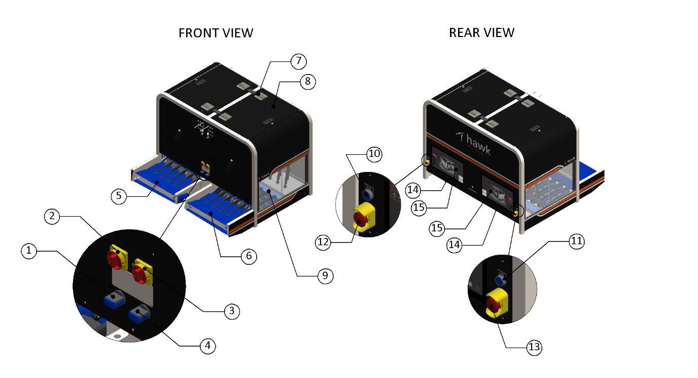
Figure 2: Dual lane packer overview
Key components:
- Left lane pneumatic isolation switch.
- Left lane electrical isolation switch.
- Right lane electrical isolation switch.
- Right lane pneumatic isolation switch.
- Left lane infeed.
- Right lane infeed.
- MCC air filters.
- MCC door.
- Door access.
- Left lane e-stop reset button.
- Right lane e-stop reset button.
- Left lane e-stop.
- Right lane e-stop.
- Touch screen user interface.
- Power buttons.
¶ Conveying and Inspection Area
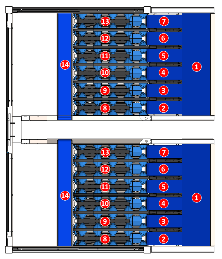
Figure 3: Conveyors top view
Key components:
- Infeed distribution conveyor
- Infeed conveyor 1
- Infeed conveyor 2
- Infeed conveyor 3
- Infeed conveyor 4
- Infeed conveyor 5
- Infeed conveyor 6
- Rotation unit 1
- Rotation unit 2
- Rotation unit 3
- Rotation unit 4
- Rotation unit 5
- Rotation unit 6
- Reject conveyor
¶ Robot Head
Robot actuators are numbered 1 to 6 (left to right when standing at the infeed), see Figure 4 below.
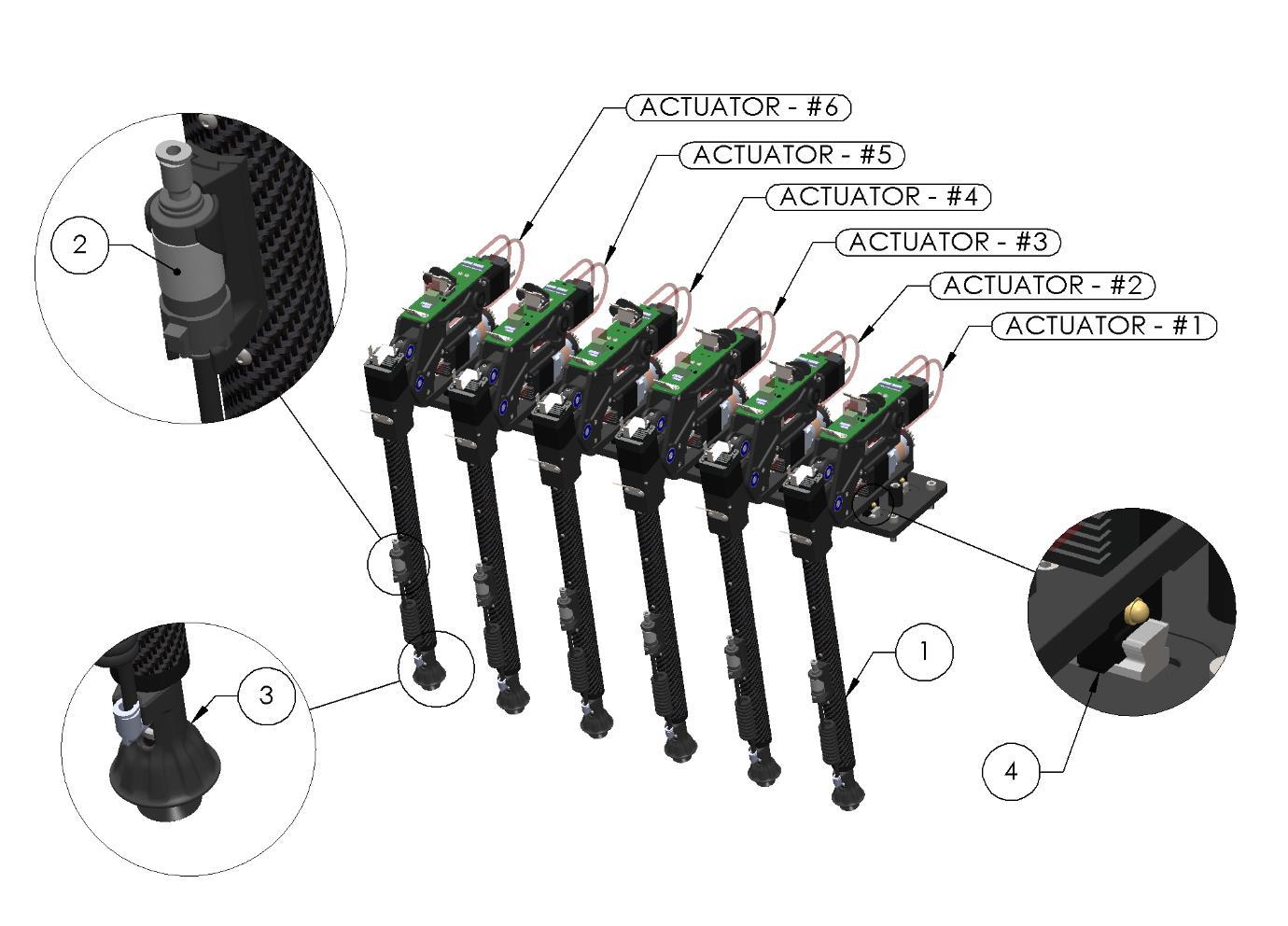
Figure 4: Robot Head
Key components:
- Picking actuator #1.
- Vacuum filter
- Vacuum cup and fruit support
- X Axis linear bearings
¶ Cleaning
The system should be cleaned as per the cleaning schedule shown in Cleaning Schedule. A comprehensive end-of-season clean should be completed to ensure the equipment is stored in a clean and hygienic state.
¶ General Cleaning Guidelines
All cleaning products should be used per manufacturer's instructions and in line with their safety data sheet (SDS or MSDS). Concentrated cleaners should be diluted as per the recommended rate, and hot water (>40°C) should not be used. Long-term exposure to chemicals should be avoided. After cleaning, the parts should be wiped or rinsed with water to remove residues.
¶ Cleaning Schedule
Table 2: Cleaning Schedule
| Location | Procedure | Frequency |
|---|---|---|
| Blue fabric conveyor belts | Remove stickers. Clean surfaces using damp cloth. | Fortnightly |
| Infeed distribution conveyor, infeed conveyors, reject conveyor | Remove stickers. Clean surfaces using damp cloth. | Fortnightly |
| Rotation unit | Remove stickers. Clean surfaces using damp cloth. For removal procedure see Rotation Unit Removal. | Fortnightly |
| Vacuum cups | Remove stickers. Clean with warm soapy water or replace if damaged. For removal procedure see Vacuum Cup Replacement. | As required |
| Vacuum filter | Clean with warm soapy water or replace if damaged. For removal procedure see Vacuum Filter or Spiral Hose Replacement. | As required |
| Vacuum tubes | Clean with warm soapy water and compressed air, or replace if damaged. For removal procedure see Vacuum Filter or Spiral Hose Replacement. | As required |
| MCC air filter | Remove, wash with soapy water, and dry before reinstallation. DO NOT USE COMPRESSED AIR. Cleaning the filters inside the packing area is critical to the reliable running of the machine, as they supply fresh air into the MCC. For removal procedure see MCC Air Filter Removal. | Fortnightly |
| Doors | Wipe with a dry, clean microfibre towel to prevent scratching. | Fortnightly |
| Camera lens covers and lights | DO NOT TOUCH OR CLEAN AS THIS WILL CAUSE DAMAGE — CONTACT TECH SUPPORT. | — |
¶ Cleaning Standard Operating Procedures
When cleaning any components with soapy water, ensure the cloth is squeezed tightly. Excessive moisture can damage the electrical components of the machine.
¶ Blue fabric and plastic modular conveyor belts
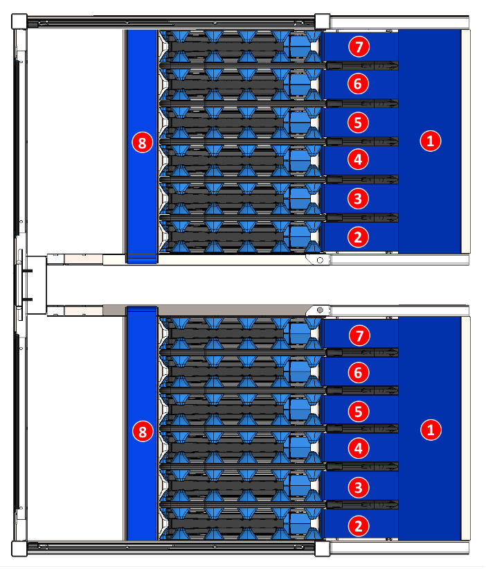
- Remove all stickers visible on conveyor belts identified 1 to 8.
- Pull the conveyors forwards until the de-stickered side is no longer visible.
- Repeat steps 1–2 until there are no longer any PLUs on all the belts.
- Clean all conveyors with warm soapy water.
- Pull the conveyors forwards until the clean side is no longer visible.
- Repeat steps 4–5 until all parts of all conveyors are clean.
- Report any damage or irregularities observed during cleaning to your supervisor or service provider. Look for issues such as torn belts, belts that move unevenly or with resistance, or belts that move too freely.
¶ Rotation unit
When cleaning any components with soapy water ensure the cloth is damp, not wet, and squeezed tightly. Excessive moisture can damage the electrical components of the machine.
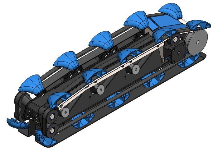
- Remove rotation units from the machine.
- Remove all PLUs. Rotate the belts so that all stickers are removed, as some may be on the underside; also check pulleys and remove stickers if present.
- Using a warm, soapy cloth, wipe down all surfaces that contact the apples.
- Clean all belts, rotating them as you clean to ensure that the entire belt is cleaned.
¶ Maintenance
The system should be maintained as per the schedule shown in Maintenance Schedule. A comprehensive end-of-season service should be completed to ensure the equipment is stored in a safe working state.
Before conducting any maintenance, always make sure the packer's electrical and pneumatic systems are switched off and de-energised using the isolation switches (see the Machine Layout overview) and appropriate lock-out tag-out procedures.
¶ General Maintenance Guidelines
All lubricants must be used per manufacturer's instructions and in line with their safety data sheet (SDS or MSDS).
Be careful not to contaminate food contact surfaces with lubricants during maintenance. If a surface is contaminated, follow the product manufacturer's guidelines on cleaning.
¶ User Serviceable Components
The items identified below can be removed and serviced by a qualified tradesperson with industrial experience. If any parts need to be replaced, please contact your Hawk Technology service technician.
¶ E-stop Testing
Test all e-stops to ensure proper functionality.
Frequency: every 2 months
Process:
Confirm that all moving parts de-energize and stop hazardous motion as intended for an emergency.
If any E-stop fails to function exactly as intended, immediately tag out the machine and replace the faulty switch component before resuming normal operation. Never operate machinery with a compromised emergency stop circuit.
¶ Rotation Unit Removal
Each of the six (6) rotation units (per packing lane) can be removed from the machine without tools. This can be helpful during cleaning.
Removal Process:
- Stop the packer.
- Open the door.
- Lift from the fruit picking end, hinging about the tail end of the rotation unit, to disengage the electrical connector.
- Once the fruit picking end is lifted clear of the reject conveyor, slide the rotation unit forward to disengage the rear location pin and remove the unit from the machine.
Installation Process:
Reverse the removal process, making sure to engage the rear location pin and not accidentally sit the tail of the rotation unit on top of the location pin.
Notes: When the door is opened, the lower half of the machine is de-energised. Be careful not to drop anything into the rotation unit data and power connector during maintenance. To protect the connector, it is recommended the rotation units are kept in place during the off season.
¶ Vacuum Cup Replacement
Each of the six (6) vacuum cups and fruit supports (per packing lane) can be removed from the machine with a 3mm hex Allen key. This can be helpful during cleaning.
Removal Process:
- Stop the packer.
- Open the door.
- Compress the pneumatic quick-lock retainer ring on the pneumatic elbow to disconnect the vacuum spiral hose.
- Rotate the pneumatic fitting head 180 degrees to expose the M4 socket head cap screw.
- Remove the cap screw and drop the vacuum head out of the machine to allow easier access to the vacuum cup.
- Slide the fruit support up the vacuum cup mount (approx. 6mm) to release the vacuum cup locking ring, then pull on the vacuum cup to remove it.
Installation Process:
Ensure the fruit support ring remains slid down the vacuum cup mount as the new vacuum cup is pressed into place. Inspect the suction cup mounting area to make sure it has seated correctly. Reverse the removal process to complete the installation.
¶ Vacuum Filter or Spiral Hose Replacement
Each of the six (6) vacuum filters and spiral hoses (per packing lane) can be removed from the machine without tools. This can be helpful during cleaning.
Removal Process:
- Stop the packer.
- Open the door.
- Unclip the top of the vacuum filter from the black retaining bracket by pivoting it forward about the bottom of the bracket. Once the top is clear of the clip, lift the filter up and out of the bottom of the retaining bracket.
- Compress the pneumatic quick-lock retainer rings to disconnect the vacuum filter or spiral hose from their fittings. Only compress the pneumatic fittings once the filter has been removed, so as not to damage the retaining bracket.
Installation Process:
Reverse the removal process.
¶ MCC Air Filter Removal
Each of the four (4) MCC air filters (per packing lane) can be removed from the machine without tools. This step is required for cleaning.
Removal Process:
- Stop the packer.
- Pull down and out on two edges of the filter that are 90 degrees from each other. This will release the plastic clips in the cover and release the filter element for cleaning or replacement.
Installation Process:
Reverse the removal process.
Notes: Ensure the cleaning procedure is followed and the filters are NOT blown with compressed air from inside the packer while in place, as this will force contamination into the MCC and could damage components.
¶ Maintenance Schedule
Table 3: Maintenance Schedule
| Location | Product | Qty | Frequency |
|---|---|---|---|
| Gearboxes | — | 6 | Sealed for life |
| Ball screw – A axis | THK MTF1002 | 6 | Yearly |
| Linear bearings – X axis | THK SR15V1SS | 12 | Yearly |
¶ Recommended Lubricants
Table 4: Recommended Lubricants
| Location | Lubricant | Special tools |
|---|---|---|
| Roller bearings | Rocol – Foodlube 2 NLGI#2 | — |
| Linear bearings | Alemlube – Lithium Grease NLGI#2 | — |
| Linear bearings | Hiwin – GNZ-05-Box | Grease nozzle kit |
¶ Operation
The packer is run from the touch screen at the front of the machine (item 14 in Figure 2). How to start, stop, empty and jog the machine, read its dashboard and change its settings is in Operation.
¶ Notifications
Faults and warnings shown on the touch screen, and how to recover from each one, are in Notifications.
¶ Release Notes
See Release Notes for what changed in each release of the machine software.